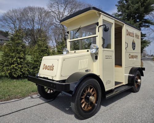
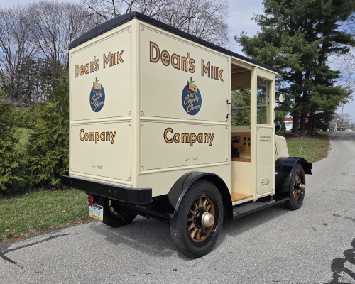
1925 Commercial Truck
Model HM-40 Battery Operated
Photos of Truck Restoration
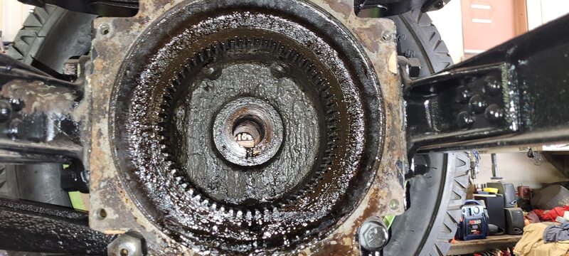
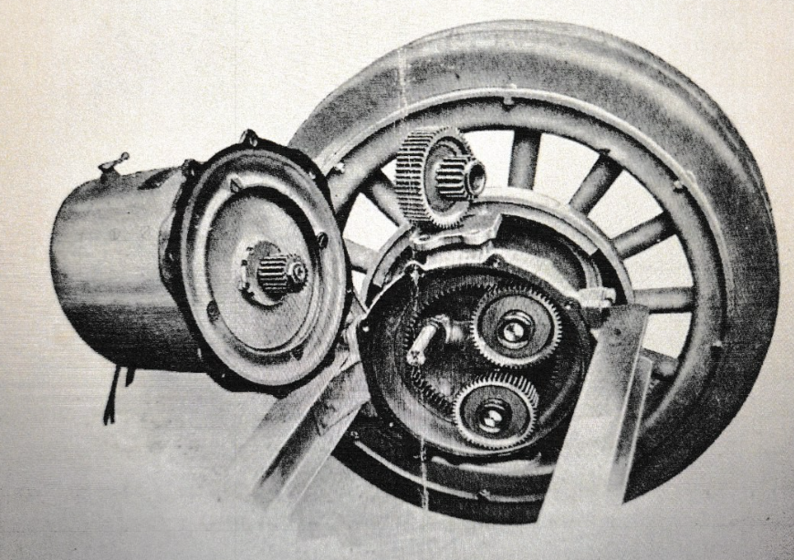
Electric motor drive gear before cleaning
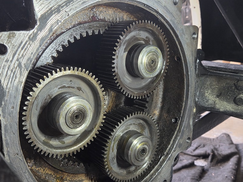
Electric motor drive gear after cleaning and assembled
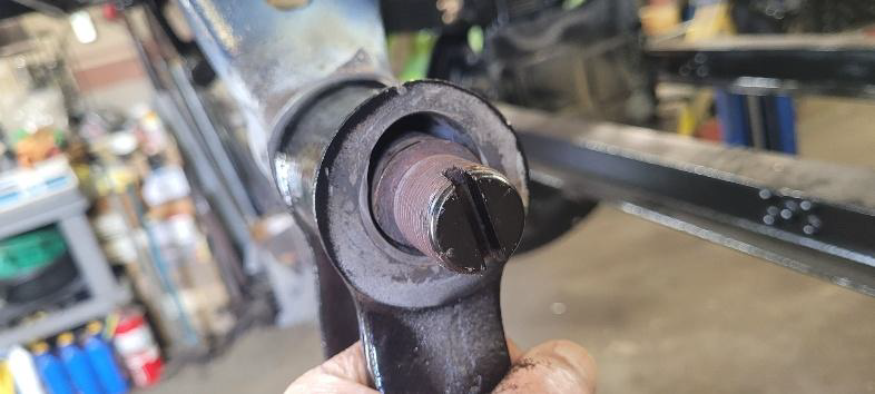
Extremely worn rear spring shackle pin bushing area
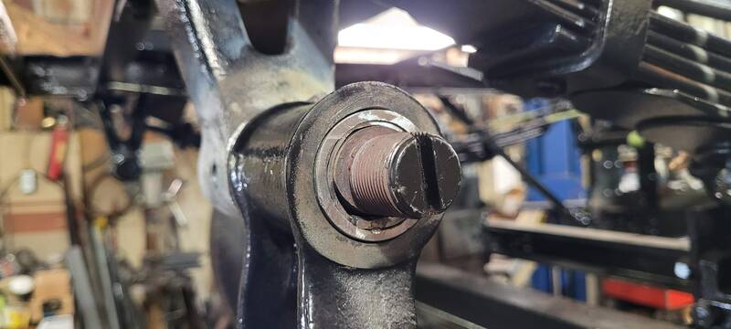
Rebuilt rear spring shackle pin and bushing repaired
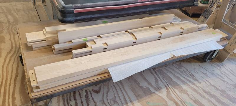
Some wood cut and ready for assembly
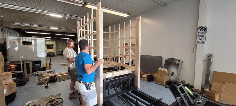
Assembling wooden body frame
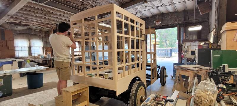
Final sanding of body before prime painting
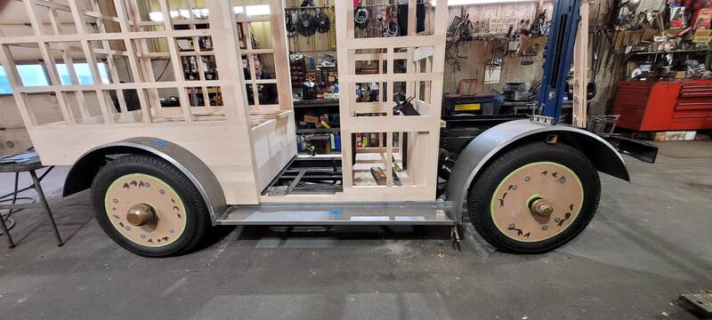
Preliminary fitting of metal work
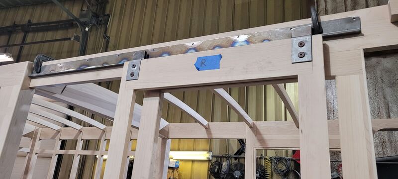
Setting upper side door roller track in place
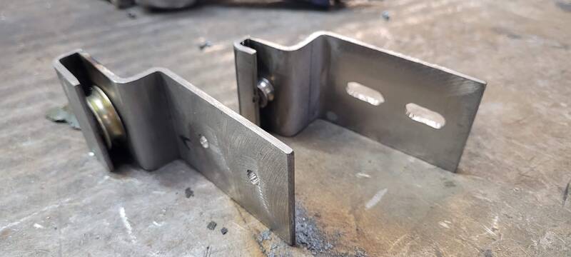
Fabricated new side door roller brackets for top and bottom
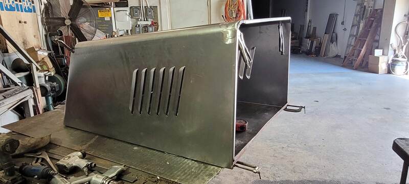
Fabricated new hood
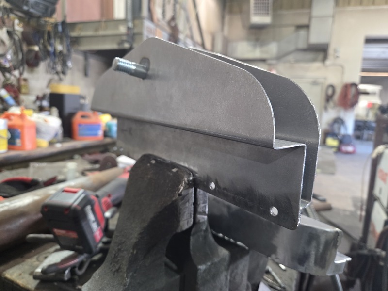
Fabricating hood support brackets
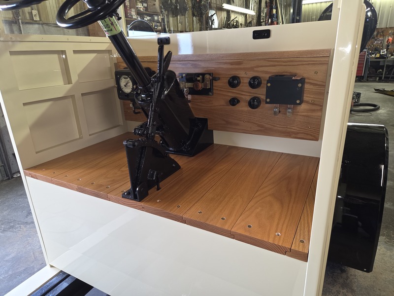
Front dash and control area
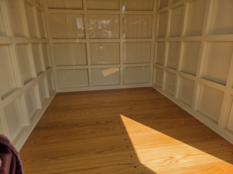
Rear cargo floor area
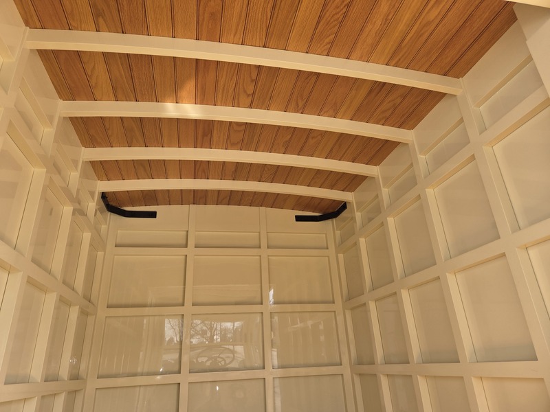
Cargo area side panels and ceiling
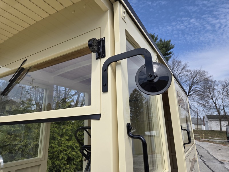
Push out windshield, manual wiper & side mirrors
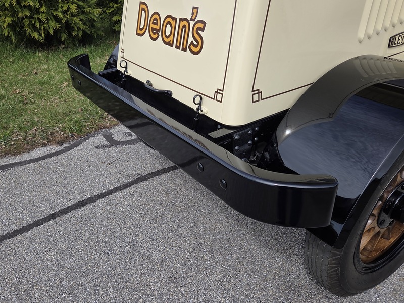
Front bumper installed
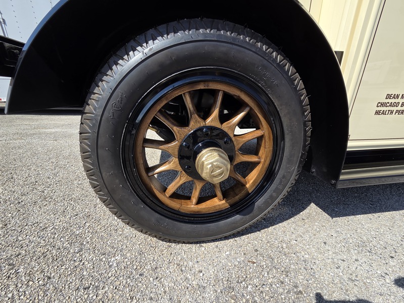
New wooden spoke wheels and cast hub cap
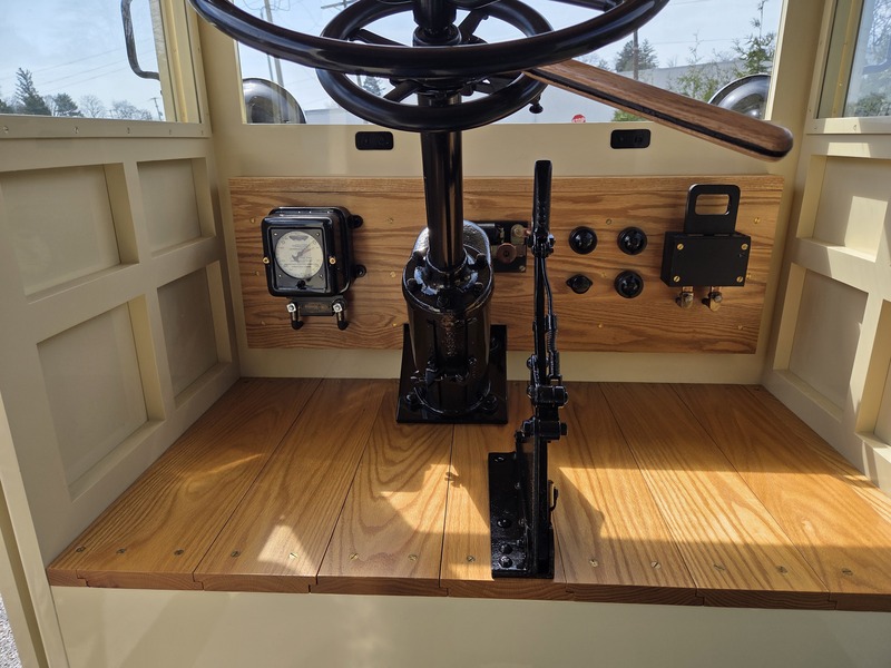
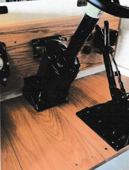
Dash board and driving controls
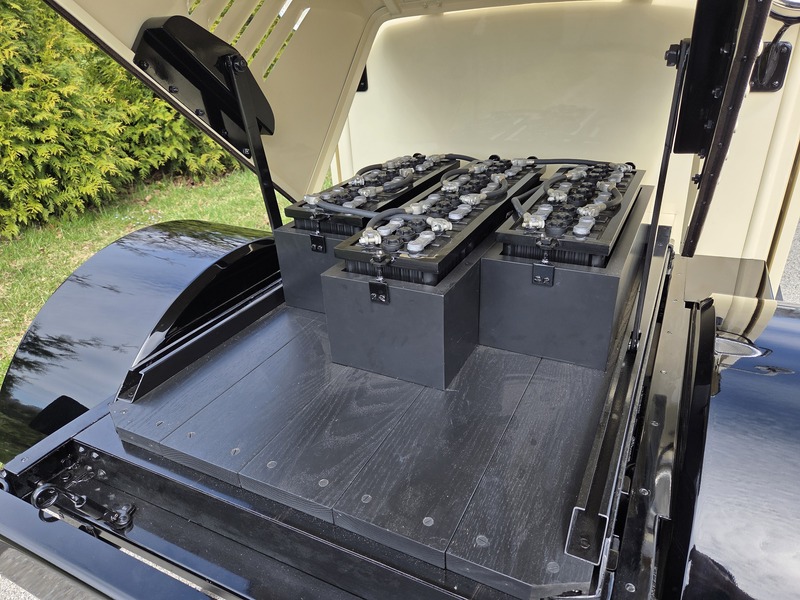
60 volt battery power for the two electric motors
Operation and History of this Truck
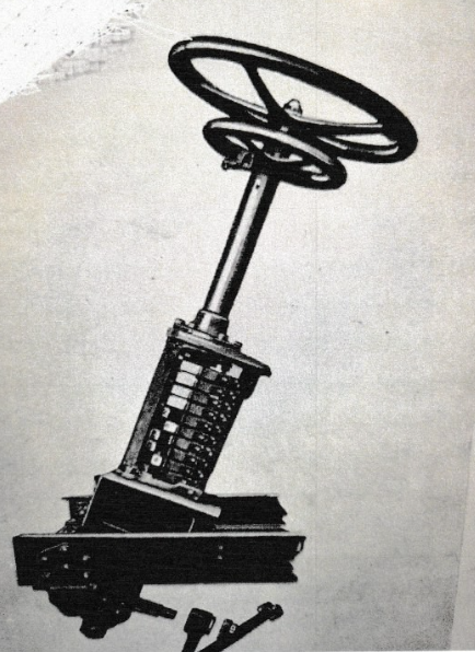
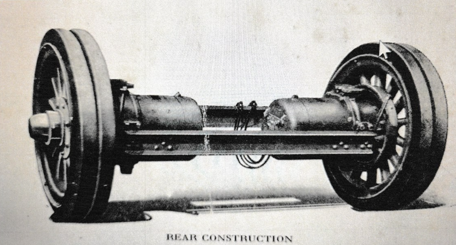
This is a two electric motor truck that is powered by a 60 volt negative grounded electric system. The two motors are mounted on the rear axle suspension system. The forward and rear speed is all controlled by the small steering wheel mounted below the normal steering wheel of the truck. Turning the little steering wheel counter-clockwise, causes the truck to move forward. The further the wheel is turned to the left, the faster it will go. The top speed on a hard level road is about 12 MPH. Turning the small “steering like” wheel clock-wise will put the truck in the reverse position and again the speed is controlled by how far to the right the wheel is turned.
The batteries are charged when the truck is not in use and connected to the regular household wiring system. The motors are low ampere rated at 22 amps.
Traveling at the maximum speed of 12 mph seems like a crawling pace for us. But back in the early 1900’s when the streets were dirt, or muddy when it rained, you couldn’t go very fast. A horse pulling a wagon at a walk is about 4 mph. If the horse would trot, the speed was in the area of about 8 mph. So 12 mph wasn’t that bad then.
Horses were being replaced by motorized vehicles. Vehicles did not require all the attention that horses did for feeding, bedding etc. Electric or battery operated vehicles were very popular in the early 1900 to 1920’s.
This truck was manufactured by the Commercial Truck Company of Philadelphia, Pa. in 1925. It is a HM-40 model, stand to drive milk truck. The original cost for this truck was $4,742.00. That was a lot of money back then. The truck was bought by Ira J. Mix Dairy from the area around Chicago, Illinois. About 1928 the Bowman Dairy Company, the largest Chicago dairy, bought out the Ira J. Mix Dairy and its trucks. Bowman’s Dairy used this truck until they were bought out by the Dean Foods Company in the late 1930’s. Dean’s used it until it was pulled out of service on March 18, 1940. It was then stored in the company’s warehouse until the Dean’s Company held their bankruptcy sale. At that time the truck was bought by Ray Alderman III, who operates a large dairy food distribution service in the Upper Mid-West Region. Ray contacted me and we formed a team to restore and display this historic milk truck. Restoration started in the fall of 2023 and was completed by early spring 2026.
Electric Drive Motors
The system of gearing used and the method of mounting ensures the load being equally distributed between the different driving gears and the alignment of the gears, and the load on the gears is not in any way affected by the spring action, road inequalities or by the twisting and weaving of frame.
This arrangement forms a symmetrical, concentric and balanced drive. The gear case being oil and dust tight, and gears running continuously in a bath of oil, ensures the maintenance of silent and efficient operation. points approximately over the axles, all being secured by rivets which are heated in place electrically by a system specially devised for the purpose by this Company and driven with an air hammer. This construction results in an extremely strong frame, and a frame that is stiff in the direction in which it should be stiff, but flexible in a horizontal plane, so that it will properly take care of the twisting and weaving due to road inequalities.
A truck with a single electric motor drive has a differential gear and all the traction is exerted to the wheel that has the poorest footing. In bad weather this causes the wheel to spin and the truck can easily be stuck or unable to move. A truck with a two electric motor drive does not have a differential gear and each motor operates independently of the other motor. Thus in bad weather if one motor looses footing, the other motor will exert its full power to keep the truck moving.
Rear Construction
Concentric gear cases of crucible steel, mounted between two axle members, are secured by heavy integral keys and bolts.
The rear springs are seated on the top of the gear cases, and the extension of the case, which is made of a die-forged, heat-treated alloy steel, forms the axle spindle.
The motor is bolted to the inner side of the gear cases in a fixed position and in line with the axle.
The armature pinion of the motor, which is made of a high-grade alloy steel and case hardened, engages three case hardened spur gears, which are carried by studs mounted integral with the driving shaft. The pinions, which are made integral with these intermediate gears, as shown by illustration, engage a single internal gear, which is pressed into and keyed to the gear case.
The driving shaft passes through the axle spindle and connects with the outer end of the wheel hub through the hub cap, which is made of heavy steel. The driving shaft has no bearing in the axle spindle, the driving gears and driving shaft being supported and held in proper position in the following manner:
The double intermediate gear has a cylindrical extension formed on its inner end exactly equal to the pitch diameter of the small gear. A cylindrical track is formed in the motor head, the diameter of which is equal to the pitch diameter of the internal gear. It will thus be seen that the three bearings form a perfect rolling support for the inner end of the driving system, the outer end of the driving shaft being supported and held central by the hub cap.
The Controller
For the safe operation of power vehicles, it is essential that all necessary apparatus be in position, easy of access and the mechanism be strong, simple and easily operated.
This is particularly true of the C-1 system of control. The steering wheel is mounted on an inclined column with the control wheel immediately below. This arrangement is simple and easy of operation, as well as safe and convenient for the driver.
The C-T controller is of special design, continuous torque and is cylindrical in shape. It is located at and forms the base of the steering column where it is easily accessible for adjustments, repairs and is out of the way, leaving the entire floor space available for loading.
The controller is extremely accessible from every point of view. One thumb screw opens the case and exposes the contact fingers which can be adjusted or replaced with an ordinary screwdriver.